Creating Programs with OpenGL
When you use a phone or a computer, you may be curious to know how they actually render graphics on to your screen. The simple answer is that they use a graphics library, with the specific variant depending on the operating system. You may not be surprised to know that Windows uses Microsoft's DirectX, while MacOS/iOS uses Apple's Metal graphics library, while most other OSs use some combination of OpenGL (standard and ES) and Vulkan.
But what do I even mean when I say 'graphics library'? Quite simply, it's just an API used to allow rendering computer graphics to some sort of display device. This doesn't strictly mean you are sending a command to the GPU, as rendering can be done entirely in software (e.g. in embedded systems) on the CPU, but it commonly means running hardware-accelerated rendering tasks using a GPU. Mind you, the GPU could still be on the CPU in the form of integrated graphics. In this blog, I will go over how to go from an empty project to rendering triangles on a window using OpenGL and a couple of other neat libraries.
Why OpenGL?
Some of you may be thinking about why I chose OpenGL, and why I develop application using it. Isn't Vulkan a better option? What about DirectX? Windows still operates on the majority of PCs, after all.
There are a few reasons why:
1. Less verbose
While this arguably could be a downside, as with other graphics libraries (may be abbreviated as GLs) you have more explicit control over rendering and theoretically get better performance out of it, I find that this is not the case. OpenGL's syntax makes it relatively easy to learn, whereas with Vulkan, the extreme amounts of boilerplate makes it much more tedious. Besides, a Vulkan tutorial would be considerably longer and more difficult to understand. And more code means more opportunity for bugs - unless you are prepared to make a full Vulkan abstractor.
2. Maximize support
This is more aimed towards proprietary vs open source; both Vulkan and OpenGL have 'open standards', so this translates to a higher percentage of support across user devices, when compared to proprietary GLs. While Windows is the dominant OS, using DirectX would require also using the Windows API, which isn't easy or good to say the least. In terms of Vulkan vs OpenGL, they both stand at over 90% support, so those would be the two best options if you want to ensure your graphical programs work anywhere.
3. Highly performant
You may be surprised to see this point. Vulkan has always been framed as the modern, performant GL and a successor to OpenGL - but is that really true, other than age? As I say in a different blog, it's about the algorithm. There is no point using Vulkan for higher performance, only to fail at properly leveraging the control that has been given to you. With OpenGL, you can still reach sub-millisecond frame times, but only if you know how to use it properly. Think about it this way - there are many "C alternatives", yet here we are, writing code in C for performance. At the end of the day, it doesn't matter how many clock cycles you have, an optimized algorithm or approach will beat an inefficient one in most cases.
Of course, I am open to discussion.
Setup
Now that we (somewhat) agree on the graphics library, we have to also discuss the version. The latest version is 4.6, but just using that has a few downsides: Apple systems do not natively support anything above 4.1 due to - you guessed it - vendor lock-in, favouring their proprietary Metal API instead. Support, naturally, decreases with higher versions, which is not want we want in this case (but I will go over newer versions in the future). Having access to the newer functions can also make programming more difficult, especially if you have an autocomplete editor, due to extremely confusing naming conventions. As a result, we will be using OpenGL 3.3, often and inaccurately called "Modern OpenGL". This has a nice balance between support and feature access, and as such, is commonly used in graphics applications like the one we will make.
I should also clarify that there are two 'profiles': core and compatibility. Core is what I will be using, as it forces us to use modern practices, whereas compatibility allows the use of deprecated functionality, such as the legacy immediate mode of OpenGL and others, and typically has worse support and performance.
Obviously, we can't just immediately start writing OpenGL code. We need to create something called an OpenGL context, which is where the OpenGL state is stored. This means we need to create a window with this context. A great library for doing such a thing is GLFW, which handles window management and input for us. This easily lets us create a window and a context in 2 simple lines of code - and it's all cross-platform, like we wanted.
Anyway, let's get on with the actual setup. First, we will create a directory for our project, and then git clone GLFW into an external directory. Git is a popular version control system used to manage large projects, and you can download Git from the official website, or you can directly download GLFW from their GitHub repository through the green 'Code' button. In terms of commands, it would look like this:
$ mkdir gl-tutorial
$ cd gl-tutorial
$ git clone https://github.com/glfw/glfw external/glfw
We also want a build system, as writing all your code in a single file is usually a bad idea (although for the purposes of this guide, all the code will go in a main.c file). As GLFW uses CMake, it is easy to integrate it into our own project with a simple CMakeLists.txt file:
cmake_minimum_required(VERSION 3.16)
project(gltutorial LANGUAGES C)

set_property(GLOBAL PROPERTY USE_FOLDERS ON)

set(GLFW_BUILD_DOCS OFF)
set(GLFW_INSTALL OFF)

add_subdirectory(external/glfw)
add_executable(gltutorial main.c)

target_include_directories(gltutorial PRIVATE external)
target_link_libraries(gltutorial PRIVATE glfw)
target_compile_definitions(gltutorial PRIVATE GLFW_INCLUDE_NONE)

set_target_properties(gltutorial PROPERTIES C_STANDARD 99 C_EXTENSIONS OFF C_STANDARD_REQUIRED ON)

if(NOT MSVC)
	target_compile_options(gltutorial PRIVATE -Wall -Wextra)
else()
	target_compile_options(gltutorial PRIVATE /W4)
endif()

if(UNIX)
	target_link_libraries(gltutorial PRIVATE m)
endif()
Now if you can't understand CMake, I don't blame you. Here's a quick rundown of the important bits:
cmake_minimum_required(...): Self explanatory - minimum required version of CMake. This is required for a CMake script.project(gltutorial ...): Creates a project calledgltutorial. This acts as a kind of 'namespace', where we can specify settings and files only for that project, and make executables and libraries. This makes linking other projects simple. GLFW has its own, which can be found in later lines. The 'LANGUAGES C' is not strictly required, and just for clarity.set_property(GLOBAL ...): MSVC quality of life setting.set(GLFW_...): GLFW-specific build settings. We are not interested in the install target or the stand-alone documentation.add_subdirectory(external/glfw): Adds the GLFW library to our CMake script. It will be compiled alongside our program, when needed (typically just once, unless you delete the build directory). Your system may actually have GLFW installed already, in which case the 'glfw' library target is already available and there is no need to compile it from source, and therefore no need for this line.add_executable(gltutorial main.c): Sets the files to be compiled into an executable.target_include_directories(...): Sets the includes directory for this project only, but I set it asPRIVATE, meaning if someone uses your project (add_subdirectory, usually if you make a library), this include will not propagate to their own compilation commands. If you want to add your own, e.g. asrcdirectory, just add it on either side ofexternal. GLFW adds it's own include directory publicly, so we will automatically be able to#includeGLFW.target_link_libraries(...): Links the GLFW library to our code, which they namedglfw. Again, I set it as private, so it only applies to our project, and not anyone else's who adds your project.target_compile_definitions(...): Adds a macro definition to our project -GLFW_INCLUDE_NONEstops GLFW from including the OS-provided graphics library headers, which typically only have an ancient version of OpenGL, and will likely conflict with our own definitions later on.target_compile_options(...): Adds a compiler option to our project.set_target_properties(...): Sets the C version to standard C99 (e.g. -std=c99, or a reasonable equivalent).
Now that we have the build system out of the way, we can finally get into the C code, and then OpenGL itself. Create a main.c file in the project's root directory and paste in the following code, which sets the GLFW error callback, initializes the library, and then terminates at the end:
#include "GLFW/glfw3.h"
#include <stdlib.h>
#include <stdio.h>

static void handle_glfw_error(int code, const char *description)
{
	printf("GLFW error %d: %s\n", code, description);
}

int main(void)
{
	// GLFW will call our function in case of any errors.
	// This could be invalid settings, unsupported features, etc.
	glfwSetErrorCallback(handle_glfw_error);

	// Initialize the library itself.
	if (!glfwInit()) {
		fprintf(stderr, "Failed to initialize GLFW.\n");
		exit(EXIT_FAILURE);
	}

	printf("Hello world!\n");

	// De-initializes the library. Note that this will also
	// destroy any active windows, of which we have none for now.
	glfwTerminate();
}
Now, to test it out. We first need to configure CMake, so it can determine what settings are applied. It's best to explicitly compile it in debug mode, since we have started development. Then, you can actually build the project, where it will compile relevant files and output the results in a given directory (commonly build, as I have set):
$ cmake -B build -DCMAKE_BUILD_TYPE=Debug
$ cmake --build build --config=Debug
If you do experience an error, and are sure it's not an issue from your own setup, feel free to contact me. Otherwise, running the executable in the output directory should produce a familiar output:
$ ./build/gltutorial
$ Hello world!
Now that everything is working as expected, we can get onto actually creating an OpenGL context, which like I said before, is where the OpenGL state is stored. Commonly known is that OpenGL is essentially a massive state machine, where you can modify it through the API and then use it to output some result. This rather outdated design choice has been partially mitigated by newer versions, such as by Direct State Access (DSA) introduced in OpenGL 4.5, but we are sticking to the not-so-modern version 3.3 for this guide.
After initialization, we need to tell GLFW what sort of OpenGL context we want, which in this case is 3.3 core. However, these are merely hints, as it is possible that your driver does not support specifically 3.3, and instead it may create a context with a higher version. Also, on MacOS, due to some support shenanigans, you need to enable a 'forward compatibility' setting for it to actually work.
Finally, we create the window using glfwCreateWindow, which takes in resolution, title, the monitor to go fullscreen in (NULL for windowed), and a context resource sharing pointer, which will also be NULL. This can fail for a number of reasons, so we also check whether the returned opaque pointer is NULL or not. The window contains an OpenGL context as well, so we go on to tell GLFW to make it the main context on the current thread with glfwMakeContextCurrent so any OpenGL (and some GLFW) calls affect our newly created window:
int main(void)
{
	// Previous initialization with glfwInit()...

	glfwWindowHint(GLFW_CONTEXT_VERSION_MAJOR, 3);
	glfwWindowHint(GLFW_CONTEXT_VERSION_MINOR, 3);
	glfwWindowHint(GLFW_OPENGL_PROFILE, GLFW_OPENGL_CORE_PROFILE);
#ifdef __APPLE__
	glfwWindowHint(GLFW_OPENGL_FORWARD_COMPAT, GLFW_TRUE);
#endif

	int width = 1280, 720;

	GLFWwindow *window = glfwCreateWindow(
		width, height,
		"Window initial title",
		NULL, // Pointer to GLFW monitor, used for fullscreen.
		NULL // Related to sharing resources between contexts, not relevant
	);

	if (window == NULL) {
		fprintf(stderr, "Window creation failed.\n");
		glfwTerminate();
		exit(EXIT_FAILURE);
	}

	glfwMakeContextCurrent(window);

	glfwTerminate();
}
Now obviously, the window is immediately getting destroyed, so let's change that with a 'main loop'. This is extremely simple, we just need a loop that runs as long as the window is open, and then we need to do two things: poll for events, which is any sort of window event, like a mouse moving across it, or the user resizing it, and to swap the (frame)buffers, which will be explained in more detail later. Also, a nice addition is to close the window whenever we press a button like ESC, as pressing the close button does get annoying over time. GLFW, being an input library, happily provides this functionality as well:
while (!glfwWindowShouldClose(window)) {
	glfwPollEvents();
	// Place AFTER we poll events so we can close as soon as the key press is registered.
	// Not really much of a difference, but it makes the logic much easier to understand:
	// Check for input/events -> Process input -> Render -> Swap buffers -> Repeat
	if (glfwGetKey(window, GLFW_KEY_ESCAPE) == GLFW_PRESS) {
		glfwSetWindowShouldClose(window, GLFW_TRUE);
	}
	glfwSwapBuffers(window);
}
Now you will see an empty window pop onto your screen with your previously set title and dimensions. However, you may have noticed we are missing something. The OpenGL API itself! There isn't a standard 'header file' for OpenGL that the Khronos Foundation (developers of the OpenGL specification) gives out. Rather, the specification is made publicly available (hence people call it "open source" or "open standard"), where a header file can be programmatically generated from said specs. The generator I use is the glad generator, which also can generate headers for Vulkan and other OpenGL variants. Using their web service we can select the Core profile (on the right), OpenGL version 3.3 (on the left, where the API is gl), and leave the other settings as is.
Once generated, download and extract the zip file, and move the KHR and glad directories into external, and the source file 'gl.c' (inside the src directory) next to your main code file.
Your project's structure should look like this:
v build
| ...
v external
|   v glad
|   |   gl.h
|   v GLFW
|   | ...
|   v KHR
|   |   khrplatform.h
CMakeLists.txt
gl.c
main.c
We can then modify both our C and CMake files to also compile and include GLAD within our project:
...
add_executable(gltutorial main.c gl.c)
#include "glad/gl.h"
// Rest of our #includes...
OpenGL, for any non-ancient version, needs to be loaded in dynamically through platform specific-means, such as dlsym, and then have every function pointer retrieved manually. OpenGL also makes use of a lot of different macros for calling functions, which GLAD does provide for us. Luckily, we don't have to worry about all of that, since to do all of this, we just need to call a single GLAD function gladLoadGL, which takes in a function pointer to some loader. Even more lucky for us, GLFW gives us exactly that with glfwGetProcAddress:
gladLoadGL((GLADloadfunc)glfwGetProcAddress);
Now we have the perfect setup for OpenGL development. Let's dive into how we can get from nothing to a triangle.
Drawing to the screen
First, we need to actually tell OpenGL the dimensions of the 'framebuffer' to operate on, which is just the dimensions of the active area of the window, with our first OpenGL function: glViewport. A framebuffer in this case is just a large grid of pixel colours (and other pixel-specific values) for the window. This has a dynamic size value as a user could - for example - resize the window, so GLFW provides a callback function for when the framebuffer size is changed (glfwSetFramebufferSizeCallback). We can easily set this up with the following:
void framebuffer_resize_update(GLFWwindow *window, int new_width, int new_height)
{
	// Takes in the parameters x, y, width and height.
	// x and y should be 0, as we want to occupy the full framebuffer.
	glViewport(0, 0, new_width, new_height);
}

int main(void)
{
	// ...

	// Register callback...
	glfwSetFramebufferSizeCallback(window, framebuffer_resize_update);
}
For a neat background colour, we need to clear the screen with said colour. This is done with glClearColor [sic]. Rendering functions are to be done in the main loop, as we want them to appear every frame. We also need to clear different screen buffers (like a framebuffer, a grid of values storing a specific property per pixel) so values don't 'leak over' from previous frames, and are instead replaced with the new values:
while (!glfwWindowShouldClose(window)) {
	glfwPollEvents();
	if (glfwGetKey(window, GLFW_KEY_ESCAPE) == GLFW_PRESS); // ...

	// Set the "color" to fill the entire framebuffer with.
	glClearColor(0.5f, 0.5f, 0.5f, 1.0f);
	// Actually clear it to the framebuffer.
	glClear(GL_COLOR_BUFFER_BIT);

	glfwSwapBuffers(window);
}
Launching the program now, we do indeed get a grey background! Try experimenting with the RGB values of glClearColor and find a combination you like! The alpha (4th) parameter is used for transparency, which we are not focusing on, so just leave it as 1.0f. Do note that this function takes 32-bit floating point values, aka a normal float.

Pipeline introduction
We need to setup a few things before we can get right into rendering shapes, first of which is a shader. What differentiates 'modern' OpenGL from the older versions is that developers have explicit control over how something gets rendered to a screen. Originally, rendering in OpenGL was a completely fixed process which couldn't be changed, hence a "fixed function pipeline" - where a pipeline in this scenario just refers to a series of calculations and checks made when rendering any object. You give it some coordinates, some colour values, normals, light information, but you couldn't really tell it exactly HOW to use that data - you could only use those 'black-box' functions given to you.
Now, we have something called GLSL - the OpenGL Shading Language. This was essentially another programming language similar to C, except it was designed to be run on the GPU. You would write this code, compile it at runtime, and the GPU would run the code to determine colour outputs, given your shape's vertices (vertex data) and other arbitrary data.
The graphics pipeline itself has multiple stages, in this order (given some sort of vertex data):
- Vertex shader - This is programmatically modifiable with GLSL code. This is usually where positions of triangles/your vertex data is calculated.
- Tessellation - Partially programmable, used to split 'patches' into more vertices where the details of each can be modified like in a vertex shader, to increase apparent detail of an object.
- Geometry shader - Also able to be changed with GLSL code, where new vertices can be added.
- Vertex post-processing - where transform feedback (when you choose to save the transformed data to the CPU) happens and the vertex data is transformed according to user-set values, such as the viewport (
glViewport), as shown previously. - Rasterization - This is when our individual "primitives" (triangles, in our case) is split up into individual "fragments". These "fragments" are just a collection of colour, depth and other values, and will typically correspond to a screen pixel, except if, for example, multi-sampling is enabled (not covered). The colour values can be edited with a shader.
- Fragment shader - Yet another modifiable one. This is where you can set the colour and depth values per fragment, as defined above.
- Per-sample processing - And finally, a lot of tests are made to check whether we should actually bother doing anything with the fragment. This includes ownership (a different window is obscuring the fragment) and depth tests (some other rendered object is in front).
We typically only need to worry about the vertex shader and fragment shader, as those are required to actually get something rendered (properly) onto the window.
GLSL coding
As said before, GLSL already has a very similar style to C, so you don't need to worry about learning a whole new language. It is better to learn with examples, rather than explaining everything with words:
#version 330

layout (location = 0) in vec3 position;
layout (location = 1) in vec2 uv;

uniform mat4 transform;

out vec2 texture_position;

void main()
{
	gl_Position = transform * vec4(position, 1.0);
	texture_position = uv;
}
A lot of this is likely new, but you may recognize a few bits: a main function complete with braces and some operations. But what is that #version at the start? What is a layout? Or a uniform?
Let's start with the top. #version is a way of notifying the driver the version of GLSL you are using. Initially, the version values were all over the place, but as of OpenGL 3.3, they unionized the versions, so for OpenGL 3.3, you would have GLSL 330, for 4.0 you would have 400, etc. This MUST be present at the start. Optionally, you can specify which profile is being used after the version number (core or compatibility), which does something similar to the different profiles of the OpenGL context itself - compatibility allows for legacy/deprecated features, whereas core cannot. By default, core is used, so it is omitted here as it is much cleaner, and core is what you would typically be using otherwise.
GLSL also has lots of new types that aren't available in C.
The layout isn't as simple. In the code, we can see two similar lines: a vec3 for position, and a vec2 for uv. This is the format of the vertex data that we pass in on the CPU side. There are also 'locations'' - these are called 'attribute indices'. Each index can support any type with at most 4 components. You could put in a mat4 (4x4 grid of floats), but this would take up 4 consecutive indices so any other data would have to be 4 indices away. However, as will be apparent later, you don't really have to be strict with matching it with your vertex data. You can tell OpenGL exactly how to interpret data with a specific function call.
As for the 'in' section, OpenGL (or your driver's implementation, to be specific) arbitrarily chooses a location by default. These don't even have to be consistent, so even if you create two separate shader 'objects' with the same underlying source code, the locations could be different. Luckily, we don't have to go through a whole mess of more functions to find out where they are located, and then changing them to what we want, and then having to store that - you can set the location directly in the shader. Here, I say that location '0' (first location possible, indexing starts from 0) will store 3 floats in the variable position. The values stored in it will correspond to the 'pattern' of locations I have given for the vertex data, using byte offset and stride parameters in CPU (aka client) code, going to the next one for each run of the vertex shader (one main function call per vertex, unless you change divisor settings; not covered here). Similar for location 1. Yes, this does mean that technically, using those aforementioned parameters, the data in both could overlap, so I could make the uv variable point to the X and Y position - not that it will be useful in any way. And as for the locations themselves, it doesn't really matter where you start - you could use location 5 and 6 for all OpenGL cares, as long as you configure the client code accordingly and don't go above the index limit - there are a really limited number of those per shader. It depends on the system, but OpenGL does guarantee at least 16, which is enough for most cases. And watch out for using the wrong type or location - you would be in undefined territory in that case, so it carries the same risk with normal uninitialized variables in C - it may look perfectly fine in your setup, but on someone else's it causes the program to crash, their entire driver to crash, or their graphics card to catch fire. So be careful!
A uniform is a variable that persists between shader calls. You can set them from the CPU side, but like the 'in' values, they have an arbitrary location. So for the client code, you would get the location by naming the variable, and then using another one corresponding to the type to give a new value. These typically store values that can change between calls, such as a value storing a time value - useful for things like raymarching.
I've talked about the 'in' variables - these represent the vertex data coming in. But what about the 'out' value? Quite simply, these variables are passed on to the fragment shader, where you would have a corresponding 'in' variable with the same name (exactly the same name - you don't get warned if they don't match, so the value will be zero or undefined. A source of great frustration!). They don't get passed in as-is though. Remember, the vertex shader is run per-vertex, but the fragment shader is run per-fragment (typically a pixel). So what about a pixel that is perfectly in between two vertices? What about one that is 20% to vertex A and 80% to vertex B? They get interpolated! This can produce very cool and interesting results if you pass in a colour value per vertex, and then send it to the fragment - you would get a whole mixture of colours between the vertices. This isn't forced, though. You can prevent this interpolation using the flat modifier, in case you are sending something like an integer or precise value.
And finally, the gl_Position variable. By default, GLSL has many standard input and output variables that are implicitly defined. These correspond to some indexing input values (gl_VertexID for the current vertex value, gl_InstanceID for the instance, not covered), as well as a few output values, most notably gl_Position. This is the final position of the vertex in 3D space, which is transformed using the user-defined view space into a 2D coordinate on your screen. OpenGL operates in relative coordinates, so you don't have to mess about with the exact pixel value. But they didn't choose for it to go (0.0, 0.0) for top-left and (1.0, 1.0) for bottom-right, like you'd expect. That would be too reasonable and simple. Instead, it goes from (-1.0,-1.0) to (1.0, 1.0) respectively. So watch out for that in case you are making some sort of UI, where you directly specify 2D coordinates rather than some arbitrary 3D position which gets transformed by those multiplications, which we will discuss later.
That was a lot of text. Let's take a break with the fragment shader now, where the main function is executed per fragment:
#version 330

in vec2 texture_position;
uniform sampler2D our_texture;

out vec4 final_colour;

void main()
{
	final_colour = texture(our_texture, texture_position);
}
Much simpler, now that we know the basics of GLSL. As previously discussed, we have our version value, a C-like main function, the texture_position corresponding to the interpolated output.
There also is a strange new type - sampler2D. This is quite simple, yet powerful. It stores a texture index, as defined in client code, and is used to 'sample' a part of a texture, given the UV coordinates in the function texture().
I also said that out variables in the vertex shader are passed on to the fragment shader. But what about now? If not already obvious from the name, it determines the final colour of the fragment - this is what will be visible on the window.
Programs and shaders
Now to actually write some OpenGL code. We want to load in both files, create two shaders for each, and link them together in a program. An OpenGL program is a linked combination of all the shaders given to it, and must be used to render anything. The main shaders needed for rendering is the two we just made: a vertex and a fragment shader.
We first need to create both shaders so they can be linked for a final resultant program. To do so, we create an empty shader object of a specific type, then give the source code, and finally compile it. It looks like this:
const char *vertex_shader_source = ... // File reading code omitted.

// Create an empty vertex shader type. A 'GLuint' is just
// an unsigned integer type used by OpenGL functions.
GLuint vertex_shader = glCreateShader(GL_VERTEX_SHADER);

// Give the vertex shader our source code. You may notice it has
// a rather strange definition: a const pointer to a string.
// This is so you can give multiple chronological code snippets
// to form the final shader; good for auto-generating shaders.
// For now, our string stores the entire code, so there is only 1 item.
// We are also not interested in the final 'length' parameter.
glShaderSource(vertex_shader, 1, &vertex_shader_source, NULL);

// Compile it! Note, OpenGL is not actually guaranteed to do everything
// you say when you say it. Driver implementations often complete tasks
// asynchronously, so actual compilation occurs when it actually is needed.
glCompileShader(vertex_shader);
We aren't done with the vertex shader yet, though. You want to check whether compilation actually succeeded or not. We can check for different status values relating to the shader with glGetShaderiv. You often see OpenGL function with names like these. The 'i' means an integer value, and the 'v' means vector, so it could contain multiple integers worth of information per parameter. Once we check, if compilation actually failed, we want to know what actually failed. The 'compilation' produces an error log in this case, similar to a normal compiler you may use, and is retrieved using glGetShaderInfoLog. You can think of it as a runtime compiler!
// If no errors were produced, our 'succeeded' variable will be 1, otherwise 0.
GLint compilation_succeeded = 0;
glGetShaderiv(vertex_shader, GL_COMPILE_STATUS, &compilation_succeeded);

if (!compilation_succeeded) {
	// Get another property of the shader - the length of the log produced.
	// It would be simpler to just store a char buffer of a reasonable length,
	// but we are showing how to retrieve other values.
	GLint log_length = 0;
	glGetShaderiv(vertex_shader, GL_INFO_LOG_LENGTH, &log_length);

	// The 'log length' also includes null terminator.
	// Malloc check omitted for simplicity.
	char *error_buffer = malloc(log_length);

	// Get and output the error log.
	glGetShaderInfoLog(vertex_shader, log_length, NULL, error_buffer);
	fprintf(stderr, "Vertex shader error: %s\n", error_buffer);

	free(error_buffer);

	// You would probably abort the program in this case.
}
And that's it. We've created a vertex shader that includes our GLSL code and compiled it. But it won't do anything on it's own. We also need to repeat the steps with the fragment shader. The code is essentially equivalent, but using the GL_FRAGMENT_SHADER type instead, and the fragment source obviously. As any programmer will tell you, repeating yourself is bad, so let's encapsulate this functionality into a generic function that takes in a source, type and returns the shader's ID (the GLuint returned by the shader creation), since that is all we need to identify the shader. I would suggest doing the same for any significant OpenGL functionality, since writing each command manually will get tedious and is extremely error-prone. You could build a whole abstraction system around OpenGL - but maybe that could be the same as recreating the OpenGL state on your client code, since all we have are quite arbitrary functions to control it.
GLuint create_shader(const char *source, GLenum type)
{
	GLuint shader = glCreateShader(type);
	glShaderSource(shader, 1, &source, NULL);
	glCompileShader(shader);

	GLint success = 0;
	glGetShaderiv(shader, GL_COMPILE_STATUS, &success);

	// To avoid large 'if' blocks, we can just return immediately on success.
	if (success) return shader;

	char buffer[1024];
	glGetShaderInfoLog(shader, sizeof buffer, NULL, buffer);

	// We have no other choice but to abort execution, so the shader can be fixed for the next run.
	fprintf(stderr, "%s shader error: %s\n", type == GL_VERTEX_SHADER ? "Vertex" : "Fragment", buffer);
	abort();
}
And now for the program itself. They are quite simple, only storing a sort of 'combined result' from all the shaders attached to it. As such, you can actually delete the shaders you just created after linking, since the program is all you need during rendering. Deleting isn't as simple as just calling a delete function. It's two functions actually. You need to first detach and then delete it, since only deleting it would schedule for the GL to do so, but only when it sees that it is no longer attached to any programs will it do so. Although the program itself no longer needs those shaders after linking, they are still attached, so you could easily change the program's results later on, for example. You should always destroy objects that you no longer need, especially considering the fact that you are essentially communicating with a black box. You likely don't know how many resources are taken up by leaving those around, especially if you are storing like a full model's vertex data. This applies to development in general - you shouldn't leave extra unused data lying around. Finally, linking itself can also fail, so you would check and log the error, similarly to the shaders above (but with program-specific functions instead). This is how you would create the program, and then cleanup the shaders afterwards, complete in a separate, reusable function:
GLuint create_program(GLuint vertex_shader, GLuint fragment_shader)
{
	// Create an empty program object.
	GLuint program = glCreateProgram();

	// Attach both shaders to it. You don't need to tell
	// it the type of the shaders; this is already stored.
	glAttachShader(program, vertex_shader);
	glAttachShader(program, fragment_shader);

	// Link the program, creating the final 'combined' result as mentioned before.
	glLinkProgram(program);

	// Similar to shaders, we also should check for errors in *linking*.
	GLint success = 0;
	glGetProgramiv(program, GL_LINK_STATUS, &success);

	if (!success) {
		char buffer[1024];
		glGetProgramInfoLog(program, sizeof buffer, NULL, buffer);

		fprintf(stderr, "Program error: %s\n", buffer);
		abort();
	}

	// Detach and delete the now-unneeded shaders.
	glDetachShader(program, vertex_shader);
	glDetachShader(program, fragment_shader);

	glDeleteShader(vertex_shader);
	glDeleteShader(fragment_shader);

	return program;
}
But there's one last thing we need to cover: the transform variable in the vertex shader. We use it in the gl_Position calculation, but what is it used for? How do you even set the value? To remind you, we have this line of code in the vertex shader:
gl_Position = transform * vec4(position, 1.0);
The reason for the multiplication (as well as the w/4th component of the vec4 being 1.0, aka the homogenous coordinate) is so we can easily transform the triangle's position, rotation and scale. In large scene editors, you don't want to modify the actual vertex data of an object every frame if you want to move something. This data is stored on the GPU (as will be discussed later on), which you don't want to be making frequent changes to. Instead, we can use a transformation matrix (also known as the 'model' matrix) and modify that. Updating a uniform is easy and relatively quick. These matrices are powerful mathematical concepts, allowing us to transform the triangle (or whatever we want) with a matrix multiplication. Do note that matrix multiplication is NOT commutative, and quite expensive.
Setting the values is quite simple. OpenGL provides dedicated functions for setting any uniform value, given that you use the correct function corresponding to the type, and that you know the location. To get the location, you can use the properly named glGetUniformLocation function. It takes in a program ID (what we just created above), and the byte-for-byte name of the uniform variable (make sure spelling is correct!). This returns a GLint value that describes the uniform's location/id relative to that program (two program can have a uniform at location X, but they would correspond to different values). Next, since they are all mat4s, we need to use glUniformMatrix4fv, meaning an array (v) of 4x4 (4) float (f) matrices. This function requires the program to be active, unlike our previous location-getting one, since that takes in a program object itself. In general, usage would look like this:
// Somewhere, we would have the program creation:
GLuint program = create_program(...);

// We named the value 'transform' in our vertex shader.
// The uniform could also be in the fragment shader - works the same.
GLint uniform_location = glGetUniformLocation(program, "transform");

// And then when rendering...

// Use/activate the program, so our glUniform* functions apply to the correct variables:
glUseProgram(program);

// Now we can set the values!
float *uniform_location = { ... };
glUniformMatrix4fv(
	uniform_location,    // Location in currently active shader
	1,                   // Array length - it's just a variable, so 1.
	GL_FALSE,            // Whether OpenGL should transpose the matrix.
	uniform_location     // The data itself.
);

// 'Transposing' a matrix is when you swap the columns and rows of it.
// Different GLs use matrices differently, so this is useful when dealing with multiple.
// We are just using OpenGL, so the matrix should be in the correct format, provided you
// use compatible libraries. More on that later.
Buffers
We need 2 things to render anything normally in OpenGL: a program, which we just made, and a VAO. VAO stands for Vertex Array Object. It stores any bound buffers and attribute indices (discussed above in vertex shader code 'locations') set whilst it was active. In older OpenGL, you didn't need this. You would just activate what state you want, and then draw - as if there was a sort of 'global' VAO. So what really is the use of one?
OpenGL makes changing different state seem really easy - usually in a single function, in fact. However, these are quite expensive, and is why doing something similar in Vulkan is extremely difficult. In Vulkan, you would precalculate the entire pipeline and use that. The shaders, rasterizer, number of viewports, depth attachments, color attachments, and a couple of other things which you don't need to code for explicitly in OpenGL. The pipelines are created so you can store its state and how it will be used for maximum performance; changing the bindings is not as simple as just 'using a different buffer'. Vulkan expect you to create all the different 'pipelines' you are going to use upfront, and then to simply keep using them. Changing something in the pipeline would usually require you to recreate it entirely.
OpenGL operates on a different format on the public API side: the pipeline state is essentially global, and you would change them with glEnable, glDisable and other similar functions. A VAO doesn't store such state, only what buffers are used, bindings and attributes. This is so you can switch between different objects with different vertex and index data with a single operation, rather than changing all the different buffers and bindings all the time.
Think of a VAO as just storing a specific combination of buffers and attributes. The buffers themselves are global, but the VAO says which ones to use and how the data is formatted. A bit confusingly, OpenGL doesn't have any functions to say 'add this buffer to the VAO', instead it is more of activating a VAO, and then any buffer which is bound or unbound will have that saved by the active VAO.
Creating objects in OpenGL follow an extremely similar and rather backwards approach. Instead of what you would expect - creating an object and then storing data in it through some sort of returned identifier, OpenGL operates by 'binding' those objects, to which operations can be direct at that 'binding point'. Quite strange and annoying, but you eventually get used to it (usually by creating a wrapper over it, so you never have to look at it again).
But what buffers do we actually need? To draw anything, you just need one: A VBO. A VBO is a Vertex Buffer Object. It stores vertex data, although it could simply be any arbitrary data. It's as simple as a couple of floats or integers corresponding to whatever you wrote for the 'in' values in the vertex shader. Let's look at an example of both the abbreviated objects being created:
// Create a VAO, with the ID stored in a variable.
GLuint vao_id;
glGenVertexArrays(1, &vao_id);

// UV data (last two floats in each row) is empty for now.
const float triangle_vertex_coords[] = {
//        X      Y     Z      U     V
	-0.5f, -0.5f, 0.0f,  0.0f, 0.0f, // Bottom-left point.
	 0.0f,  0.5f, 0.0f,  0.0f, 0.0f, // Top-middle point.
	 0.5f, -0.5f, 0.0f,  0.0f, 0.0f  // Bottom-right point.
};

// Generate a generic buffer, with the ID stored yet again in a variable.
GLuint vbo_id;
glGenBuffers(1, &vbo_id);

// Bind the VAO, so any buffer configurations are saved to it.
glBindVertexArray(vao_id);

// Bind the buffer to the currently bound VAO.
// The bound VAO essentially stores the IDs bound to different
// 'binding points' - in this case, the binding GL_ARRAY_BUFFER (aka a VBO)
// will now store the created buffer.
glBindBuffer(GL_ARRAY_BUFFER, vbo_id);

// Buffer (allocate and set) the data to the buffer at the GL_ARRAY_BUFFER binding.
// I know, quite weird. You would expect it to just take in an ID, like in DSA.
// The last value is an often unused hint that describes how the buffered data
// will be used. GL_STATIC_DRAW means:
// 'this will be modified once and used many times (STATIC) for drawing (DRAW).'
glBufferData(GL_ARRAY_BUFFER, sizeof triangle_vertex_coords, triangle_vertex_coords, GL_STATIC_DRAW);

// Some other configurations, which will be shown in the next code blocks.

// Unbind it, to avoid leaking state. Optional, but great for avoiding bugs.
glBindVertexArray(0);
It's important to note that glBufferData replaces any current data (we don't have any currently; it's a newly created buffer). It's like a free then a malloc operation, except with a GPU data store. If you want to replace a given section, you should use glBufferSubData, which has an offset parameter but no hint, since the hint is used on allocation of the buffer to determine the best location for the given data. Again, in terms of C code, using it's like a memcpy operation - you just insert the data at the location specified by the start byte offset and size, but you can't resize the actual underlying buffer.
You may be wondering what is meant by 'state leakage'. For any bind operation, using an ID of 0 rather than one generate by the respective function will unbind it, so no object is associated with that binding point or state. If you try to do something with that binding point, you would get an error. This ensures that you do not operate on the wrong object.
On the topic of errors - how do you even know if an error occurred? A simple function is provided for us - glGetError(). This returns an enum that describes the most recent error that occurred, like popping from some sort of error list. This could be an invalid operation (GL_INVALID_OPERATION), an OOM error (GL_OUT_OF_MEMORY), or something else. It is best to wrap this error checking functionality in a macro, for simplicity. In the case of getting an OOM error, you should immediately abort rather than trying to do some clever memory cleanup, since the GL likely runs asynchronously, as mentioned previously; and as such you are already deep into undefined behaviour territory, as stated by the specification. There is also a controllable callback that runs in case of any errors, but this is only available in higher OpenGL versions.
Now that we have both created, we need to actually configure how the data is actually used. Currently, to OpenGL, we just gave it a bunch of bytes. We need to tell it how that data should be used, in relation to the attribute indices used by shaders. If you remember, we have a vec3 position at attribute location 0, and a vec2 uv at attribute location 1. You may be tempted to assume that since that totals to 5 floats in a consecutive order, it should treat the data as such and work flawlessly. But the GL doesn't know anything about our data, it's a void pointer. How does it know whether we actually gave it floats? What if we didn't want to use every nth float? What if there is extra data? We need to tell it the exact format of the data to retrieve for every attribute: for position, it is 3 floats starting from byte offset 0 (it's at the start), and these 3 floats are found every 5 floats (remember, there are 2 other floats for UV data), and for the uv data, it is 2 floats starting from 3 floats ahead of the start (skipping position floats), and also found every 5 floats.
In code, we would use the glVertexAttribPointer() function. As described, this is how we tell OpenGL the exact locations of data that a given attribute will use from our vertex buffer. But here's another thing: the glVertexAttribPointer applies to the currently bound VBO and VAO. This allows us to separate individual properties into separate vertex buffers, perhaps if it is more convenient to update for you, or for other rendering techniques like instancing (not covered). But usually you would store all data in a matching order to the attributes in the program, like we are doing here. Lastly, you need to also enable that attribute with glEnableVertexAttribArray(), so it actually uses it.
Here's an overview of the parameters, and an explanation of how to use it programmatically:
void glVertexAttribPointer(
	GLuint index,         // attribute index
	GLint size,           // component count (i.e. vector size)
	GLenum type,          // type of value
	GLboolean normalized, // for fixed-point normalization, ignore
	GLsizei stride,       // bytes between consecutive position/uv data
	const void *offset    // byte offset of first piece of position/uv data
)
// At this point, our VAO and VBO are currently bound, so the following configs
// apply to this specific buffer in this specific VAO.
// We could bind a different buffer and then apply different configs, such as
// to store all position data in one VBO and configure attribute 0 for that,
// and create another for UV data and configure attribute 1.
// We aren't doing this however, and using the standard method of one VBO.

// Our buffered data looks like this: X Y Z U V X Y Z U V X Y Z U V
// As you can see, the first 'position' value (X Y Z) is at the very start,
// and each next position data is 5 floats from the start of the previous.

// Repeating attribute from vertex shader:
// layout (location = 0) in vec3 position;
// Think of the functions like this:
//
// At enabled attribute index *0*, we want *3* components of type *GL_FLOAT*.
// They are not fixed-point values, so are not to be normalized to [-1, 1] range (GL_FALSE).
// They are found every *5 floats* from each other, with the first starting at a 0 byte offset.
glEnableVertexAttribArray(0);
glVertexAttribPointer(0, 3, GL_FLOAT, GL_FALSE, 5 * sizeof(float), (const void *)0);
// Equivalent to: glVertexAttribPointer(0, 3, GL_FLOAT, GL_FALSE, 20, NULL);

// Similarly for this one:
// layout (location = 1) in vec2 uv;
//
// At enabled attribute index *1*, we want *2* components of type *GL_FLOAT*.
// Again, not normalized. They are found every *5 floats* from each other, with
// the first starting at a 3 float byte offset (aka after first position).
glEnableVertexAttribArray(1);
glVertexAttribPointer(1, 2, GL_FLOAT, GL_FALSE, 5 * sizeof(float), (const void *)(3 * sizeof(float)));
// Equivalent to: glVertexAttribPointer(0, 3, GL_FLOAT, GL_FALSE, 20, (const void *)12);
If the explanation and comments weren't enough, here's a diagram made by yours truly (thanks draw.io!).

Our first triangle
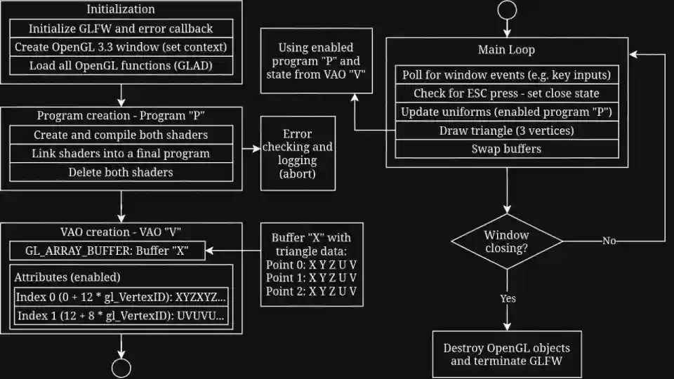
And now to combine all of them together! We need to create a program, a VAO, a VBO, setup attributes, setup the transform uniform, then actually draw the triangle.
Since we just want to see the triangle as-is, the 'transform' matrix can just be an identity matrix - that is, a matrix where everything is 0 except for 1's along the diagonal. We already have the functions for program and shader creation, and we can then combine all the buffer and attribute code.
Since the code is getting a bit complex, this calls for yet another diagram, this time of the whole program!
Sources
Some great resources for additional help can be found below. This page wouldn't exist without them!